Listening for the Crack
Catching fatigue in a shaft that never stops
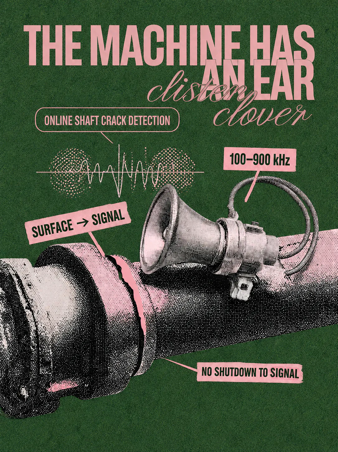
10
Year — 2022
Categories
Role
- Research placement — SCGC (SCG Chemicals)
- ME capstone project — Chulalongkorn University (team of 6)
- Failure analysis, method trade study & experiment design
A shaft in SCGC’s pellet dryer had already failed once by rotating-bending fatigue, and the only way to inspect its replacement was to pull it — three days of stopped production every time. The brief asked us to prove ultrasonic testing could catch the crack while the machine ran. Twelve weeks of stress analysis, a three-way method trade study, and a costed bill of materials answered with something else: listen to the shaft instead.
Problem
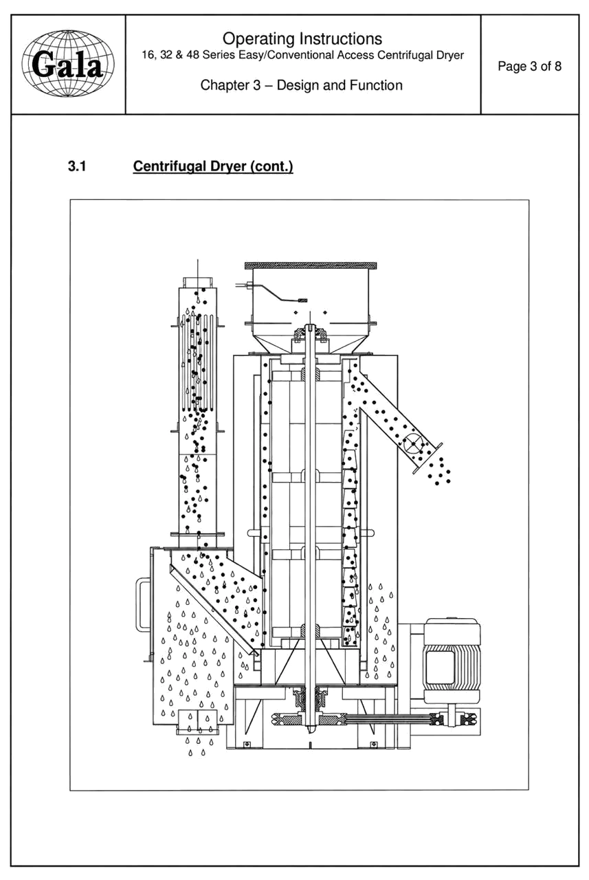
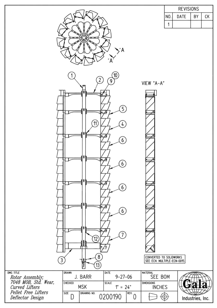
The pellet dryer turns a 17/4 PH stainless shaft at 280 rpm under 5,800 N of belt tension, carrying 700 kg per rotor tier and moving 62.5 tonnes of plastic pellet an hour. When a crack starts in that shaft, nobody finds out until it comes out of the machine — and taking it out costs at least three days of stopped production, on top of whatever the crack damages on its way to failing.
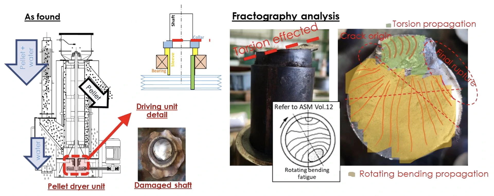
SCGC had already lost one shaft and had the fracture surface to prove how it went: origin at the outer surface, beach marks fanning across the section, torsion at the far edge, then final rupture. What they wanted next was not another post-mortem. They wanted warning — enough notice to schedule the swap, and enough confidence to run a shaft past its nameplate life because the remaining life was known rather than assumed.
Failure analysis
Before choosing an instrument we had to know where to aim it. The shaft was reduced to a free-body diagram under the belt load and solved for its bearing reactions — FB = −5,914 N, FA = 114 N — then carried through torque, shear, and bending-moment diagrams along its length.
Two locations competed to be the weak point: the groove and the bearing seat. Each got a full fatigue check — stress-concentration factors applied to the alternating bending and mean torsional stress, von Mises equivalents, a Marin-corrected endurance limit for surface finish, size, temperature and 99% reliability, then a modified Goodman criterion. The groove returned a safety factor of 8.34 against the bearing seat’s 17.87. The groove is where it breaks, and it breaks in rotating bending — independently reaching the conclusion the fracture surface had already recorded.
The brief named ultrasonic testing. The trade study answered with acoustic emission — the same 0.75 mm sensitivity, at 41% of the cost.
Method
Three techniques can see a crack in a turning shaft: ultrasonic testing, acoustic emission, and vibration analysis reading the natural-frequency shift a crack introduces. Vibration went out first, for a specific reason rather than a general one — every published result we could find had been obtained on journal bearings, and this machine runs ball bearings. With no evidence that the frequency comparison survives that difference, the method could not be relied on.
The remaining two were scored against gates instead of opinions. Both detect rotating-bending cracks, both mount at the shaft end, both work at 280 rpm, and both resolve a crack down to 0.75 mm. Ultrasound wins on characterisation — it can describe the flaw, where acoustic emission needs a time series to infer size. Cost settled it: against a 100,000 THB ceiling, the ultrasonic build priced at 207,922 THB and the acoustic-emission build at 85,000 THB. Acoustic emission also delivers the thing actually being asked for — a signal that rises before fracture, not a measurement taken after.
Analysis
- Downtime per teardown inspection
- 3 days
- Safety factor at the groove
- 8.34
- Safety factor at the bearing seat
- 17.87
- Smallest detectable crack
- 0.75 mm
- Detection methods evaluated
- 3
- Selected build vs ultrasonic
- 85k vs 208k THB
The instrument
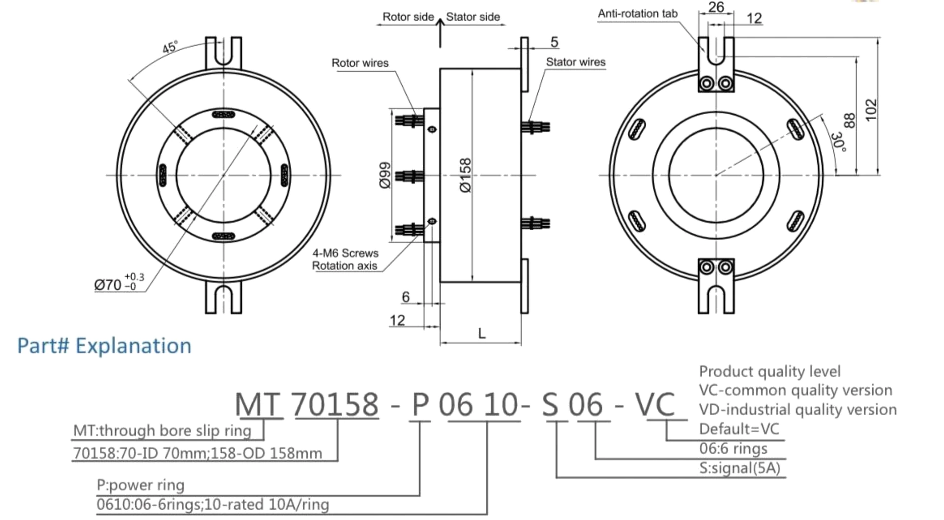
The sensor has to ride the shaft, which means its signal has to get off a rotating part. A Vallen VS900-RIC acoustic-emission sensor — 100–900 kHz, specified wider than the 100–400 kHz standard band because the shaft-crack literature reports useful content above 400 kHz — sits on a machined holder clamped below the collar, bonded with Loctite 407 and retained by a set screw. Its cable feeds the rotor half of a Moflon through-bore slip ring whose 70 mm bore matches the shaft exactly; the stator half is held against rotation by a stopper rod anchored to the same base as the bearing. Downstream sit a 34 dB AEP5 preamplifier and an ASIP-2 processor with 18-bit conversion and high- and low-pass filtering.
All of it had to fit the 280 mm of clear space between the collar and the underside of the pellet drum — without modifying the machine.
The experiment
A design is a hypothesis until something tests it, so the final deliverable was the rig and the protocol. The rig rebuilds the real lower shaft at full diameter — 70 mm, a true-scale shoulder, two ball bearings, collar and sleeve, and the same belt and motor at the same belt tension — on a 500 mm shaft short enough to sit on a bench.
Three conditions. An uncracked shaft at 281 rpm first, to record what a healthy shaft sounds like. Then the same shaft notched to 0.75 mm, the detection floor, to confirm the sensor sees it and to isolate the crack’s acoustic frequency as the band whose amplitude departs from baseline. Then the crack is grown in 1 mm steps — and here the arithmetic earns its place. Crack growth tracks revolutions, not clock time, so running the rig at 5,000 rpm instead of 281 compresses each millimetre of growth into 44 hours, against the 1,033 million revolutions a real shaft survives over seven years. Sampling the signal at every step is what turns an amplitude into a remaining-life estimate.
Outcome
What the project delivered is a fully specified, costed, buildable detection scheme and the experiment that would qualify it — not a working instrument. The twelve weeks ran out before the rig could be built, and the report says so plainly: every component was selected from parts that can be bought or manufactured, so SCGC could carry it forward.
The value is in the reasoning rather than the hardware. A client-named method was tested against alternatives and replaced on evidence. A fracture surface was corroborated independently by hand calculation that also located the critical section. And a set of physical constraints — 280 mm of space, a sensor that has to spin, a fixed budget — was converted into a specific bill of materials. Treating a brief as a hypothesis to be tested rather than an instruction to be followed is the transferable part.
- SCGC (SCG Chemicals) & Chulalongkorn University, Mechanical Engineering
Next case study
11 / 11